Why? While it’s similar to a class diagram, it takes a deeper dive, describing the internal structure of multiple classes and showing the interactions between them.
#Violet uml editor tutorial software#
This is seldom used by anyone outside the software development field. Connectors define the relationship/dependencies between the different components.Ĭomposite structure diagram. Each of the pieces is shown using a rectangular box, with its name written inside.

In other words, it gives a more simplified view of a complex system by breaking it down into smaller components. Also known as a component flow diagram, it shows logical groupings of elements and their relationships. In other words, will it work in practice? It shows a system’s objects and their relationships and offers a better view of potential design flaws that need fixing.Ĭomponent diagram. Often, this diagram is used as a way to doublecheck a class diagram for accuracy.

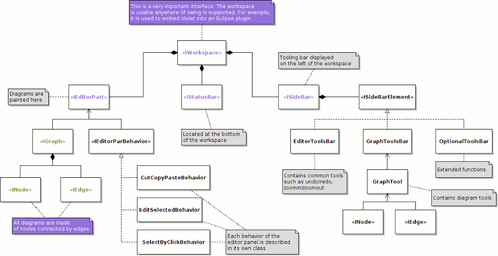
Bottom section: class methods or operationsĮxample of UML class interface diagram.This diagram offers a visual of the different classes and how they are interrelated, and each class has three compartments: It looks similar to a flow chart because the classes are represented with boxes. This diagram, the most common type in software development, is used to depict the logical and physical design of a system and shows its classes. Let’s take a closer look at the many different types of UML diagrams that fall under each category: 1. These diagrams show the functionality of a system and emphasize on what must happen in the system being modeled. The focus here is on dynamic aspects of the software system or process. These tools offer guidance and ensure that all parts of a system work as intended in relation to all the other parts. They show the hierarchy of components or modules and how they connect and interact with each other. These are used to help you visualize the various structures that make up a system, like a database or an application. Structural diagrams represent the static structure of software or a system, and they also show different levels of abstraction and implementation. Let’s take a closer look: Structural diagrams


The goal is for UML to visually express diagrams that are easy for everyone to understand. That means each layout requires a different focus and level of detail. These variations exist to represent the numerous types of scenarios and diagrams that different types of people use.įrom customers and project managers to technical authors, designers, analysts, coders, and QA, testers, each role will utilize a specific diagram to suits their needs. There are two major types of UML diagrams: structure diagrams and behavioral diagrams (and within those categories lie multiple others).


 0 kommentar(er)
